As utilities prepare for the pending 4-ppt PFAS drinking water MCL, many are discovering that legacy lead/lag designs—workhorses for decades when treating contaminants in the ppm and ppb range—simply are not optimized for the parts per trillion-level (ppt) precision PFAS demands. The challenge is not just about removing PFAS; it is about managing the Mass Transfer Zone (MTZ) with far greater control than traditional “cookie-cutter” treatment skids were ever built to provide.
Sentinel Water Solutions has approached the problem from a different angle: custom-engineered treatment skids built around hydraulic loading rate (HLR), flow variability, empty bed contact time (EBCT), and the unique behavior of PFAS breakthrough curves. By designing systems around the way PFAS actually behaves—not around a fixed skid footprint—we enable utilities to optimize MTZ progression, maximize media utilization, and reduce total cost of ownership.
Why PFAS Treatment Requires More Than a Standard Skid
In standard packaged systems, tank diameter and height are predetermined. Flow must be forced to fit the equipment rather than the system being engineered around the flow. This disconnect is manageable for contaminants with sharp breakthrough fronts—but PFAS, with its elongated mass transfer zone, exposes the inefficiencies in oversimplified designs. In fact, many PFAS pilot studies have demonstrated PFAS MTZs that stretch 70-80% through the lead bed on Day 1 of operations, primarily because removal is now required at levels 1000x more granular than the ppb treatment levels typically required of traditional lead/lag systems.
Two realities consistently challenge off-the-shelf PFAS systems:
1. HLR and EBCT Targets Are Fixed
Many vendors only provide 1 vessel height for a given vessel diameter, resulting in inefficiencies. By allowing for custom vessel heights Sentinel can engineer systems to better deliver media-specific EBCTs. Regulators typically require the following EBCTs for PFAS treatment systems:
- GAC: 20 minutes
- IX: 5 minutes
If your vendor only provides cookie-cutter systems they will often upsize your system to hit the required EBCT- resulting in higher CAPEX costs along with increased backwash and rinse volumes due to use of larger diameter vessels.
2. Lead/Lag Systems Don’t Perform the Same at PPT Levels
At ppt concentrations, the MTZ for PFAS is far longer than traditional contaminants measured in ppm or ppb concentrations. Lead/lag configurations—highly effective for decades—often force a premature media changeout because regulatory thresholds are hit long before the lead vessel is meaningfully exhausted.
The Hidden Cost of Cookie-Cutter Systems: Oversized Valve Trees
Another challenge frequently overlooked in standardized skids is valve sizing. Because many pre-packaged systems are engineered to serve both IX and GAC applications within the same skid footprint, manufacturers often install oversized valve trees to cover the widest possible range of flows.
This “one-size-fits-all” approach can result in:
- 8-inch valve assemblies in applications where a 4-inch valve tree is hydraulically appropriate
- Significantly increased upfront capital costs
- Larger building footprints
- More difficult servicing due to the size, complexity, and long lead times for large-diameter replacement components
When right-sized, a fully automated 4-inch valve tree often costs the same—or even less—than a manual 8-inch configuration. The smaller, task-specific valve tree is not only more ergonomically manageable but also benefits from:
- Shorter replacement part lead times
- Better maintainability
- More compact layouts, which is critical for well houses and space-limited municipal facilities
Sentinel avoids the inefficiencies built into traditional skid offerings by designing valve trees in parallel with the custom tank design. This ensures utilities pay for the valves they need, not oversized hardware required only because a skid was designed to be all things to all sites.
Custom Tanks Built Around Flow — Not the Other Way Around
Sentinel designs each vessel beginning with site-specific hydraulic loading requirements rather than predetermined skid templates.
Step 1: Establish the Target HLR and Select the Optimum Tank Diameter
GAC and ion exchange beds perform optimally within specific hydraulic loading rate (HLR) ranges—typically:
- GAC: 2–10 gpm/sf
- IX: 6–18 gpm/sf
We engineer tank diameter so that the system remains within HLR limits across BOTH:
- Permitted design flow, and
- Actual instantaneous flow variability
Most well sites experience significant swings between permitted flow and real-world instantaneous flow. If the vessel diameter is fixed, these fluctuations can push systems outside the target HLR, shrinking effective EBCT, and resulting in channeling that reduces media life.
Where swings are too great for one train to accommodate, parallel treatment trains with active flow controls may be recommended.
Step 2: Determine Tank Height to Achieve Required EBCT
Once the diameter is set, height is engineered to deliver media-specific EBCT. By providing custom tank heights, EBCT is a controlled design variable—not an accidental byproduct of a prefabricated vessel. All too often we see clients who get stuck with oversized systems when their vendor only provides vessels with standard heights, and aside from the additional CAPEX costs associated with the larger system there are also several operational inefficiencies. Consider this real-world example where a client had to upsize their GAC vessels to a 10-ft diameter system vs. a custom-built 8-ft diameter system.
Backwash And Rinse Volume Comparison, 8-FT vs. 10-FT Diameter System:
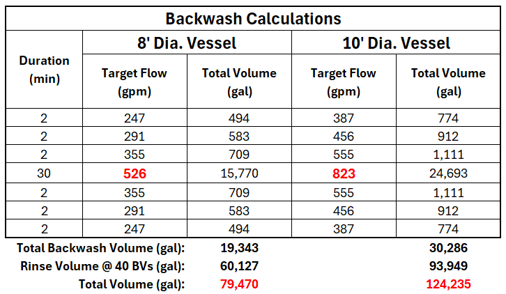
The volume required to backwash and rinse each vessel (to achieve arsenic and pH conditioning) are both increased over 50% by upsizing the vessel- resulting in additional waste management costs for the life of the system. The required flow rate to achieve 30% bed expansion for 30 minutes is also increased which can result in the need of additional storage depending on your system configuration.
Engineering for an Extended MTZ: Why 3+ Vessels Often Outperform Lead/Lag
For sites with elevated PFAS concentrations, Sentinel frequently recommends a Roughing Filter configuration where we deploy three or more vessels in series. This design allows the MTZ to progress through the lead vessel and better ensures the media is fully loaded before regulatory triggers occur downstream.
Consider a site with 12 ppt PFOA:
- A traditional lead/lag system may require a media changeout as soon as the lag vessel effluent reaches 4 ppt, even if the lead vessel is far from exhausted.
- A 3-vessel train better captures the MTZ, allowing full exhaustion of the lead vessel and reducing O&M costs.
MTZ Illustration:
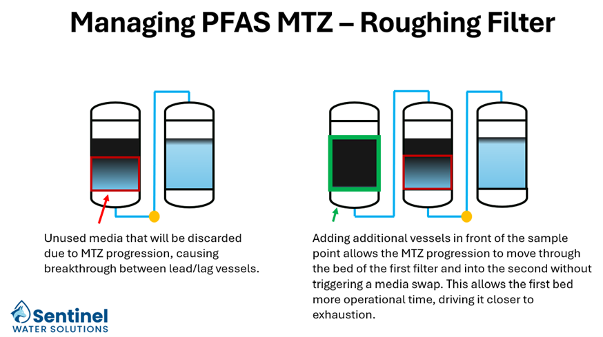
This configuration can also drive vessel size down by spreading the EBCT across more vessels, enabling full-vessel swaps—an approach with significant operational benefits, particularly for sites with limited waste-handling options or constrained footprints.
Retrofitting Existing Systems: Custom Valve Trees and Add-A-Vessel Options
Many legacy PFAS systems were designed before the 4-ppt horizon came into view. As a result, utilities often face:
- Frequent media changeouts
- Short run times
- MTZ behaviors outpacing system design
- Premature breakthrough caused by flow variability
Sentinel provides custom valve trees and retrofits—including add-a-vessel and mixed-media train solutions—to help utilities adapt cost-effectively while maintaining their existing assets.
A PFAS System Designed for Reality—Not Assumptions
PFAS treatment at ppt levels requires engineering discipline far beyond traditional cookie-cutter designs. Sentinel’s custom vessels, right-sized valve trees, and MTZ-focused system layouts give utilities the precision needed to meet upcoming regulatory requirements while optimizing long-term operational economics.